Factory combinations, not guesswork.
This guide summarizes the engine, transmission, transfer-case, and axle-ratio combinations printed in Chevrolet’s 1976 Pickup “Power Teams” sheets, printed pages 27–28, each dated January 16, 1976. It is a guide to documented factory availability. It is not proof that any component now installed in a particular truck is original.
On this page: Engines and ratings · Transmissions and axle ratios · Component identifiers · Front-axle BOM lookup · Sources
What the factory record can establish
The data book shows which powertrain combinations Chevrolet offered by pickup series. Used with a genuine, VIN-consistent SPID label, build sheet, invoice, or warranty record, it can help determine whether a claimed configuration was possible and whether the vehicle documents agree.
A casting number can help identify an engine, transmission, transfer case or axle design. It cannot tell you whether that part left the factory in your truck. To make that connection, look for dates that fit, assembly markings, any vehicle-specific numbers, evidence that the component stayed with the truck, and supporting paperwork.
1976 Chevrolet pickup engine availability
Table source: Chevrolet Motor Division, 1976 Chevrolet Truck vehicle information kit, “Pickup / Power Teams,” printed pages 27–28 (PDF pages 30–31), each dated January 16, 1976. The engine, rating, transmission, transfer-case, and axle tables below are transcribed and interpreted from those two pages; the listed codes are availability evidence, not proof of a particular truck’s original equipment.
On a phone, swipe the tables sideways to see every column.
F44 denotes heavy-duty chassis equipment.
| Engine | RPO | Carburetion | Pickup availability shown | Important limit |
|---|---|---|---|---|
| 250-cu.-in. inline six | LD4 | 1-barrel | C10 without F44; C10 with F44; K10 | Light- and heavy-duty-emissions ratings differ. |
| 292-cu.-in. inline six | L25 | 1-barrel | C10 with F44 (California only); C20; C30; K20 | C10/F44 availability requires California Emission Certification. |
| 350-cu.-in. V8 | LF5 | 2-barrel | C10 without F44 | LF5 is not a universal 350 code. |
| 350-cu.-in. V8 | LS9 | 4-barrel | C10 without F44; C10 with F44; C20; C30; K10; K20 | Published output varies by emissions class. |
| 400-cu.-in. V8 | LF4 | 4-barrel | K10; K20 | Shown only with M40 Turbo Hydra-matic and NP203. |
| 454-cu.-in. V8 | LF8 | 4-barrel | C10; C20; C30 | No K-series pickup application appears in the Chevrolet chart. |
California limits apply to individual combinations. Page 27 marks the LD4 250 in C10/F44 and the LF5 350 two-barrel and LF8 454 in C10 without F44 as unavailable for California registration. Other marked rows require California Emission Certification. Keep the source’s symbols and footnotes with a proposed combination rather than applying one rule to every use of an engine code. Pickup Power Teams, printed Page 27 (PDF 30).
Published SAE-net ratings
| Engine and emissions class | Net horsepower | Net torque |
|---|---|---|
| 250 six, light duty | 105 at 3,800 rpm | 185 lb-ft at 1,200 rpm |
| 250 six, heavy duty | 100 at 3,600 rpm | 175 lb-ft at 1,800 rpm |
| 292 six, heavy duty | 120 at 3,600 rpm | 215 lb-ft at 2,000 rpm |
| 350 2-barrel, light duty | 145 at 3,800 rpm | 250 lb-ft at 2,200 rpm |
| 350 4-barrel, light duty | 165 at 3,800 rpm | 260 lb-ft at 2,400 rpm |
| 350 4-barrel, heavy duty | 165 at 3,800 rpm | 255 lb-ft at 2,800 rpm |
| 400 4-barrel, heavy duty | 175 at 3,600 rpm | 290 lb-ft at 2,800 rpm |
| 454 4-barrel, light duty | 245 at 3,800 rpm | 365 lb-ft at 2,800 rpm |
| 454 4-barrel, heavy duty | 240 at 3,800 rpm | 370 lb-ft at 2,800 rpm |
| 454, California footnote | 250 at 3,800 rpm | 385 lb-ft at 2,800 rpm |
The factory table specifies SAE net ratings at 85°F. Light-duty-emission engines are limited there to C10 pickups without F44.
Transmissions and transfer cases
| Component | Factory designation | What the recovered chart establishes |
|---|---|---|
| Three-speed manual | M15 | Factory availability in Chevrolet pickup power-team rows. |
| Three-speed manual | MC1 | Factory availability in Chevrolet pickup power-team rows. |
| Four-speed manual | M20 / Chevrolet CH465 | In this truck source, M20 identifies the CH465 four-speed—not a passenger-car Muncie assumption. |
| Turbo Hydra-matic automatic | M40 | Factory availability; mandatory with LF4 in the K10 and K20 rows. |
| New Process transfer case | NP205 | Paired with manual transmissions in the recovered K-series combinations. |
| New Process transfer case | NP203 | Paired with M40; mandatory in the LF4 K10/K20 combinations shown. |
These pairings establish what Chevrolet listed as available. They do not identify a component presently installed in a truck. Verified unit-number locations and the remaining decoding gaps are distinguished in the physical-identification section below.
Why some 1976 four-wheel-drive trucks have no locking hubs
Chevrolet’s August 29, 1975 engineering leaf describes two arrangements. Its full-time four-wheel-drive system, used with a V8 and Turbo Hydra-Matic in the stated model context, has an interaxle differential in the transfer case and is described as unavailable with free-wheeling front hubs. The same leaf describes HUB/LOK free-wheeling hubs as standard on K10/K20 models with manual transmissions. The transfer-case differential is separate from the front and rear axle differentials.
For a surviving truck, record visible hub controls, transfer-case identification and vehicle-linked paperwork separately. The hub appearance alone does not establish the original drivetrain or whether its internal configuration has changed.
Source: Chevrolet Motor Division, 1976 Chevrolet Truck information kit, Axles, Suspensions & Steering, printed page 3 / PDF 34, August 29, 1975. These are dated factory-system descriptions, not current operating or modification instructions.
Axle-ratio codes printed in the chart
| Ratio | Printed code | Current reading |
|---|---|---|
| 3.07 | HE3 | Verified code-and-ratio pairing |
| 3.40 | HE4 | Verified code-and-ratio pairing |
| 3.73 | GT4 | Verified code-and-ratio pairing |
| 4.11 | HO4 | Verified printed code-and-ratio pairing |
| 3.21 | HC8 | Verified code-and-ratio pairing |
| 4.10 | GT5 | Only rear-axle entry shown in the K20/LF4 row |
| 4.56 | HC4 | Verified code-and-ratio pairing |
The chart also states that a locking rear axle was available, but it does not establish the precise locking-differential RPO and all application restrictions. For model-specific G80 ordering restrictions, see the RPO and Option Guide. The chart names Chevrolet rear axles and lists capacities. Its dual-rear-wheel footnote identifies a Dana 7,500-lb rear axle; the companion axle specification limits the pickup application to C30 Fleetsides with Z81/Z83. The power-team footnote excludes a locking differential for that application. These general notes do not identify a surviving truck’s housing casting, tube stamp, installed gearset or complete supplier history. Pickup Power Teams, printed Page 27, January 16, 1976 (PDF 30); Axles, Suspensions & Steering, printed Page 9, August 29, 1975 (PDF 40).
Ratio-code scope. Read an axle-ratio code within its model-specific table. Chevrolet’s January 16, 1976 van Power Teams sheet prints HE4 beside 3.42 in the G10 header and beside 3.40 in the G20 header. The pickup guide’s HE4 = 3.40 entry is therefore pickup-scoped; it is not a universal all-truck decimal decoder. These printed associations do not establish the gears currently installed in a surviving vehicle.
Source: Chevrolet Motor Division, 1976 Chevrolet G-Van vehicle information kit, Chevy Van Power Teams, printed page 14 / PDF page 15, January 16, 1976.
Three corrections worth preserving
LF4 and LF8 are not interchangeable
For Chevrolet pickups in the recovered 1976 chart, LF4 is the 400-cu.-in. four-barrel V8 and is shown only in K10 and K20 pickups. LF8 is the 454-cu.-in. four-barrel V8 and is shown only in C10, C20, and C30 pickups. A claimed factory LF8/454 K-series Chevrolet pickup requires a different market’s primary document before it can be accepted.
M20 does not mean the same thing in every GM application
The Chevrolet truck chart explicitly identifies M20 as the Chevrolet CH465 four-speed. Decoding it solely from passenger-car usage produces the wrong conclusion.
A casting number is not a vehicle identity
An engine-block, transmission-case, or differential casting can narrow a component family. It cannot prove “numbers matching,” the assembly date, or original installation in a particular truck without stronger markings and vehicle-specific evidence.
Reading physical component identifiers
An ordering code, an assembly marking, a casting number and a vehicle-derivative stamp answer different questions. Preserve each complete marking and its location before comparing it with a source of the same model-year and application scope. A compatible code does not establish original installation or the parts currently inside a component.
Keep a history for each component
A restoration record is more useful when it preserves what was observed and how it was interpreted. For each marked component, keep four short entries:
- Observed mark. Copy the complete visible text, its physical location and the photograph date, if known. Record unclear characters as unclear.
- Reference. Name the manual or catalog, its date and page, and the exact part description and application. Distinguish a number read from the part from one found only in a catalog or invoice.
- Known history. Keep dated installation, replacement or rebuilding records with the component. Identify an owner’s recollection as an account when supporting paperwork is absent.
- Finding. State separately what the evidence supports about the component’s identity, its date and its association with this truck. Leave an unsupported field unresolved.
For example, GM’s February 1983 truck parts catalog illustrates separate V-belt fields for the part number, ID code and vendor; that illustration supplies no date-code legend. Its standard-belt charts cross-reference production number 9433638, code BQ, to service number 9433741, code FX. A documented replacement can therefore have a different number and code. This is a later service reference, not a production change date or proof of what a particular 1976 truck originally carried.
A useful entry might say: “Mark photographed; cited service application matches; installation date and original vehicle association unknown.” The carburetor and axle examples below explain why even a matching mark can need service-history context.
Source: General Motors, Light Truck Parts Catalog 51, effective February 1983, group 1.066, printed 1-12 C and 1-13 C / retained PDF pages 238–239. The selected standard-belt charts exclude special notched belts. This example is a historical identification cross-reference, not a present-day parts-selection instruction.
Engine unit numbers and suffixes
Chevrolet’s 1976 service supplement locates the six-cylinder unit-number pad on the right side of the block behind the distributor, and the V8 pad at the front right of the block. Its worked example, F1210TFA, identifies Flint and December 10, followed by the truck and transmission/engine-type portion. It does not give a year field or decode that example into a particular 1976 engine application. The pad instructions are general six-cylinder and V8 statements, rather than a separate location diagram for every engine option. [S1, service 0-1 and 0-3 / PDF 7 and 9]
Later factory evidence supplies a model-year-specific suffix chart. Catalog 51, revised February 1983, lists 39 C/K rows in its 1976 chart: seven for the 250, six for the 292, fifteen for the 350, four for the 400 and seven for the 454. These are displacement, model and qualifier entries, not a complete engine-RPO crosswalk. For example, the 350 entries TKF and TYC expressly specify two-barrel carburetion; the other 350 rows cannot all be assigned to LS9 merely because they omit that wording. NB2 and H.D. Chassis qualifications must remain attached to their rows. The 454 C20/C30 TH400 entry excluding NB2 reads TSD. [S4, TP17 / printed 17 / PDF 21]
Catalog 51 also describes a vehicle-number derivative on the engine and transmission of Series 10-35 trucks, consisting of division number, model year, assembly plant and vehicle sequence. That note gives no engine stamping location, complete literal example, field widths or division-number decoder. It does not establish the engine unit-number pad as the derivative’s location. [S4, TP7 / printed 7 / PDF 11]
Production-fit markings. An undersize crankshaft does not automatically establish a later rebuild. Chevrolet’s 1974 overhaul manual, used with the 1976 supplement, describes a production-fitting condition involving .009-inch-undersize main journals. It identifies that condition with .009 on the crankshaft counterweight forward of the center main journal and 9 on the block’s left-front oil-pan rail. These specific marks describe production fit in that source; they are not year or plant codes and cannot establish the original internals of a surviving engine.
Sources: Chevrolet 1974 Overhaul Manual, ST-333-74, printed 6-19 / PDF 167; Chevrolet 1976 supplement ST-330-76, foreword / PDF 5 and engine-overhaul section opening / PDF 307.
Emission-label context. Keep a sufficiently authenticated Vehicle Emission Control Information label with the component evidence. In its idle-speed discussions, Chevrolet’s 1976 service supplement directs readers to that label for the latest certified specifications and says they may differ from the manual. A difference in that context does not automatically invalidate either source. This does not reconcile unrelated carburetor-model discrepancies, authenticate a replacement decal, or establish an individual engine’s original installation.
Source: Chevrolet ST-330-76, printed 6M-7 / PDF 95 and printed 6M-40 / PDF 128.
Two different “evaporation” systems
Chevrolet’s 1976 service supplement distinguishes ECS, the Evaporation Control System, from EFE, Early Fuel Evaporation. ECS manages gasoline vapor from the tank through a separator, storage canister and connecting controls. EFE uses exhaust heat beneath the carburetor to improve cold-engine warm-up. The similar names describe different equipment.
For the EFE equipment described in the supplement, the six-cylinder engine uses an oil-temperature-operated thermal vacuum switch in the right-hand oil gallery. The small-block V8 and 454 V8 use coolant-temperature sensing; the general description locates the switch on the inlet manifold, while the V8 component paragraph specifies the coolant outlet housing or front of that manifold. Keep the switch, exhaust-heat valve and actuator distinct when describing photographed components. These historical descriptions do not establish current condition, original installation or interchangeability.
Source: Chevrolet Light Duty Truck Service and Overhaul Supplement, ST-330-76, copyright 1976: service Section 6T opening, indexed 6T-1 with no printed folio / PDF 163, ECS; service 6T-5 / PDF 167, EFE and switch locations.
Rochester carburetor identification
Chevrolet’s 1976 service supplement locates the 4MV and M4MC/M4ME part number on a vertical section of the float bowl near the secondary throttle lever. Its 4MV illustration points to the marking.
A later parts listing can distinguish variants without dating the change. Delco bulletin 9C-3060T, July 1978, page 1, lists 17056115 and a separate “LATE” 17056117 for 1976 Federal C10 pickups with the 350-cu.-in. engine, 2GC carburetor and manual transmission. The page gives no production-date or VIN cutoff. Its 1978 revision date belongs to the publication. These retrospective application entries do not decode physical date markings or prove original installation.
Specifications 13 lists 7045213 for Federal HD 350/LS9 applications in C10–20–30 and K10–20 under both manual and automatic transmissions. California number 7045583 also appears in both columns. These 1976 application entries show why a prefix or odd final digit cannot replace the exact table row; they do not date an installed carburetor.
The M4MC/M4ME section anticipates transferring the number when replacing the float bowl, so a matching stamp alone cannot establish an original bowl. Date markings need separate review: the 1974 base manual’s 4M illustration labels model number, plant, shift, year and day of year. The 1976 supplement expressly refers 4MV overhaul to that manual, but the older illustration does not establish a universal later stamping format.
Sources: Chevrolet Motor Division, General Motors Corporation, 1976 10–30 Series Truck Chassis Service and Overhaul Manual Supplement, ST-330-76, copyright 1976: service 6M-31 / PDF 119, M4MC/M4ME location and replacement-bowl statement; service 6M-54–55 / PDF 140–141, figure 1Q, 4MV location; Specifications 13 / PDF 383, application table; overhaul 6M-1 / PDF 309, 4MV reference to the 1974 manual. Chevrolet Motor Division, 1974 Passenger Car and Light Truck Overhaul Manual, ST-333-74, copyright 1973: 6M-2 / PDF 188, figure M1, 4M identification view. PDF pages are one-based; retain the named service or overhaul half.
Component markings and High Energy Ignition (HEI) wires
The 1976 Chevrolet truck service supplement places the starter’s serial number and production-date stamping on the outer case toward the rear, and the Delcotron’s unit serial number at the top of the rear housing. It describes the HEI spark-plug wires as orange, 8 mm and silicone-insulated. These are documented identification details and period specifications; matching them alone does not prove a component is original to a truck.
Source: Chevrolet Motor Division, 1976 Chevrolet 10–30 Series Truck Chassis Service and Overhaul Manual Supplement, ST-330-76: printed 0-3 / PDF 9, starter and Delcotron markings; printed 6Y-10–11 / PDF 182–183, HEI definition and wires.
Chevrolet’s 1976 service supplement describes two High Energy Ignition (HEI) arrangements: the eight-cylinder distributor has its ignition coil inside the cap, while the six-cylinder version uses an externally mounted coil. Its separate illustrations identify both as HEI.
An external coil therefore does not, by itself, establish a conventional points ignition on the six-cylinder application described here. Conversely, that component layout is not a complete distributor model/date identification and cannot authenticate the ignition currently fitted to a truck.
Source: Chevrolet ST-330-76, service 6Y-10 / PDF 182, General Description and Figures 1i–2i, View the service supplement page . The cited passage supplies configuration context within this truck manual, not wiring, testing or retrofit instructions.
HEI part identification. For the six- and eight-cylinder engines covered by this Chevrolet manual, service page 6Y-14 describes a yellow retainer, called a “bow,” holding the white and green pickup-coil leads. This is a replacement-part identification cue. The yellow refers to the retainer; the spark-plug wires described above are orange. The cue gives no distributor calibration or manufacturing date and cannot prove original installation. This passage does not establish broader GMC or all-GM application. Source: ST-330-76, service 6Y-14 / PDF 186.
Starter manufacturing context. Delco-Remy’s brochure for its October 27–28, 1977 open house identifies Anderson Plant 3 as producing starting motors for cars and light trucks, among other applications. This documents a 1977 manufacturing location; it does not identify the plant that made an individual 1976 truck’s starter.
Source: Delco-Remy Division, General Motors, October 27–28, 1977 open-house brochure, Anderson Plant 3 entry. Scan hosted by the independent Delco-Remy History archive.
Transmission unit and serial locations
The 1976 supplement gives these physical locations:
- Three-speed unit number: lower left of the case, beside the rear of the cover
- Four-speed unit number: rear of the case, above the output
- TH350 unit number: right-rear vertical surface of the oil pan
- TH400 serial number: light-blue plate on the right side of the transmission
The three-speed instruction is generic; a separately verified Tremec-specific location is still missing. These location statements do not supply a character-by-character production, calibration, serial or date decoder. M15, MC1, M20 and M40 remain ordering/application codes, distinct from a physical unit number. [S1, service 0-1 and 0-3 / PDF 7 and 9]
For pan-stamped TH350 units, the carried-forward 1974 overhaul instructions direct the production code to be transferred from the old pan when a replacement pan is fitted. That 1974 note also lists JA/JH governor-cover exceptions; it does not establish their 1976 application. A pan marking therefore needs service-history context. Catalog 51 offers another broad identification aid: mechanical throttle control on the right side for TH350, and electric control on the left for TH400/TH475. That later catalog distinction neither separates TH400 from TH475 nor authenticates an individual unit. [S3, 7A-70 / PDF 290; S4, printed 4-27 / PDF 597]
Production and replacement parts. In its Turbo Hydra-Matic 375/400/475 section, Chevrolet’s 1976 supplement describes production-built direct-clutch pistons without a check ball and service replacement pistons with one. Models CL and CZ have a two-check-ball service piston exception. Production pistons may be aluminum or stamped steel. The page separately describes a check ball in the direct-clutch housing, so record which part was observed. It gives no date, transmission serial-number or VIN cutoff for the change. Neither the material nor a matching feature proves original installation in a truck. This passage does not show that every 1976 truck used one of these transmissions, and it is not current repair guidance. Source: ST-330-76, overhaul 7A-9 / PDF 361; section heading, 7A-3 / PDF 355.
NP205 front-output designs
GM’s February 1983 Catalog 51 distinguishes two NP205 front-output designs. Its first-design entry for the listed 1973–77 three-/four-speed manual applications identifies a front-output yoke and 10-spline front-output shaft. A separately listed 1977 second-design entry identifies a front-output flange and 30-spline shaft. These are front-output features, not transmission-input spline counts. The catalog supplies service-assembly numbers 3990935 (NP10105) and 471711 (NP10976) for those respective entries. They are service-parts cross-references, not a decoded unit serial number or assembly date. The entries do not establish an exact production changeover, extend the second-design listing to 1976, or prove which components were originally installed in a surviving truck.
Source: GM Light Truck Parts Catalog 51, group 4.505, printed 4-67 / PDF 637, REV. 2-83. Independent GMPartsWiki scan.
Radiator identifiers
The factory service manual illustrates radiator-code location separately from transmission-oil-cooler connections. Its cooler description is qualified, so that drawing cannot establish a universal manual-versus-automatic identification rule. Later service numbers also need care: the 1983 catalog assigns 3030125 to both 1976 C1/292 automatic applications without A/C/V01 and manual applications with V01. This service-number match does not establish original installation, a production date or present replacement suitability.
Sources: Chevrolet 1974 service manual ST-330-74, printed 6K-3 / PDF 431 and printed 6K-4 / PDF 432; 1976 supplement, section 6K opening / PDF 85; Catalog 51, printed 1-3 C / PDF 229, REV. 2-83.
Axle markings and source limits
Axle-size evidence. A ring-gear diameter or axle type name is not a complete vehicle identifier. Chevrolet’s 1976 axle chart lists 10½-inch Salisbury rear axles across C20, K20 and C30 applications, with different source and capacity entries. Its C20 entry excluding Crew Cab carries 5,700 lb, while the Crew Cab entry carries 7,500 lb. Both Chevrolet- and Dana-sourced C30 entries also appear at 10½ inches and 7,500 lb, separated by the chart’s Dual Wheel Camper qualifier. Those are axle-chart descriptors, not a substitute for the vehicle’s GVWR or evidence of a survivor’s current safe capacity.
Source: Chevrolet Motor Division, 1976 Chevrolet 10–30 Series Truck Chassis Service and Overhaul Manual Supplement, ST-330-76, section 4 opening leaf / PDF 47, Figure 1, Axle Chart. Retain the chart’s “Except Dual Wheel Camper” and “Dual Wheel Camper” qualifiers.
Catalog 51 supplies rear production-code formats and a 1976 series-specific code table. As a limited K20 example, RFN/RFZ is listed with 4.10 gearing, RFR/RHZ with 4.10 and the catalog’s locking-differential descriptor, RFU with 4.56, and RFW with 4.56 and that descriptor. The table has no RPO column or complete per-code GVW, brake, engine or body breakdown. A housing code cannot establish which gears remain inside it. [S4, TP23 / printed 23 / PDF 27; 1976 portion of TP27 / printed 27 / PDF 31]
The rear location sources do not agree in every detail. The 1976 service list places the Series 10/20 and P30 marking at the front of the right-rear tube and gives additional carrier/dual-wheel instructions. The 1983 catalog distinguishes Corporation 10-series front-right-tube, Corporation 20-30 top-right-tube, and Dana rear-surface right-tube locations. Retain the source difference rather than claiming one universal 1976 location. The catalog’s Corporation example has no separate year field; its Dana date example is explicitly a 1975 illustration. [S1, service 0-1 / PDF 7; S4, TP23 / printed 23 / PDF 27]
For K10/K20 front axles, the expressly carried-forward 1974 service text places the assembly number and production date on the left tube. The referenced overhaul page describes a cover-bolt tag carrying drive-gear and pinion tooth counts. Those are housing-associated identifiers, not proof of the present internal gearset or original vehicle association. Complete 1976 front-axle production-date/source-character decoding and exact changeover remain unresolved. [S1, service section 3 opening / PDF 45 and overhaul section 3 opening / PDF 297; S2, 3-38 / PDF 216; S3, 3-1 / PDF 23]
Retrospective Spicer front-axle BOM lookup
Spicer’s retrospective manufacturer-hosted axle catalog supplies a suffix-specific front-axle Bill of Material (BOM) number lookup for the listed 1976 and 1976½ K10/K5 and K20 applications. Read the full number, including its suffix, against the model/year heading. The table labels the selected rows Standard and prints 4.09 and 4.55 where shown; those values should not be silently normalized to other GM tables. This establishes the catalogued application, not the truck in which an axle was originally installed or its present internal gears.
“Standard” is the source’s differential-type label, not a claim that each ratio was standard vehicle equipment. The “1976½” heading supplies no exact changeover date or serial breakpoint and no demonstrated mapping to GM’s first-/second-design housing rows.
| Listed application | Front-axle BOM | Suffixes and listed ratios | Source locator |
|---|---|---|---|
| 1976 K5 Blazer, K10 1/2 Ton Pick-up & Station Wagon on Truck Chassis | 603706 | -1 and -2: 3.07 -3 and -4: 3.73 -5 and -6: 4.09 | Printed 117 / PDF 124 |
| 1976½ K5 Blazer, K10 1/2 Ton Pick-up & Station Wagon on Truck Chassis | 603675 | -1 and -2: 3.07 -3 and -4: 3.73 -5 and -6: 4.09 | Printed 117 / PDF 124 |
| 1976 K20 3/4 Ton Pick-up & Station Wagon on Truck Chassis | 603707 | -1 and -3: 4.55 -8 and -9: 4.09 | Printed 119 / PDF 126 |
| 1976½ K20 3/4 Ton Pick-up & Station Wagon on Truck Chassis | 603676 | -1 and -3: 4.55 -8 and -9: 4.09 | Printed 119 / PDF 126 |
Source: Spicer axle catalog, manufacturer-hosted 253-page PDF, selected tables at printed 117 / PDF 124 and printed 119 / PDF 126. The retrieved manufacturer-hosted file combines a March 1990 X510-8 DSD cover, X510-8 contents with ©2004 Dana Corporation, and X510-9 headers on the cited tables. These cues do not establish a pure March 1990 edition or exact table revision date.
No housing service part number or casting-number equivalence is established. Do not infer the absence of an unlisted original-build configuration from these retrospective selected rows.
Service markings and replacement references
Steering and brake records. GM’s February 1983 Catalog 51 lists steering gears separately from housing assemblies: 7828050 is described as a housing assembly, not identified there as a cast-in number. Keep the catalog’s component description and application with any number recorded from a service invoice. Physical marks also need service context. The 1976 Delco brake-booster overhaul instructions expressly include housing staking during reassembly, so visible stakes alone cannot establish an untouched factory assembly. [S4, 6-17 and 6-38 / PDF 945 and 966; S1, overhaul section 5 opening / PDF 301]
Internal axle marks. The Dana 10½-inch rear-axle instructions distinguish etched ring-and-pinion matching numbers from the separate plus/minus/zero pinion-face mark used for depth adjustment. Matching numbers are also checked on a new service gear set; they do not prove the pair was installed when the truck was built. The Power-Lok instructions separately call for a scribed case-half alignment mark during servicing. These internal marks cannot substitute for an exterior axle application code or a manufacturing-date legend. The 1976 supplement carries the 1974 procedures forward subject to its stated changes. [S3, 4-45, 4-55 and 4-58–59 / PDF 77, 87 and 90–91; S1, overhaul section 4 opening / PDF 299]
Delcotron ratings. The 1976 generator table lists V8/K79 model 1102841 at 42 amps rated hot output and V8/K76 model 1102480 at 61 amps. It has separate L6 model numbers and separate cold-output figures; those columns must remain distinct. The carried-forward service text identifies rated output as a frame stamping. A rating, a table’s model number and a unit serial number answer different questions; a model-year application does not decode a component’s calendar manufacturing date. The August 1975 pickup booklet also describes Z56 with a 55-amp generator and separately lists K76 with Z56, so Z56 alone does not establish 61 amps. [S1, Specifications 17 / PDF 387 and service section 6Y opening / PDF 173; S2, 6Y-22 / PDF 562; S7, pp. 32–33]
Fuel-source scope. The 50-gallon tank illustration in the 1976 supplement is explicitly for P30, not a C/K pickup auxiliary tank. The August 1975 NL2 entry’s approximate 16-gallon description and the September brochure’s wheelbase-specific 16/20-gallon wording remain unreconciled; their publication dates alone do not establish a hardware changeover. Read each source’s model and option qualifications with its capacity statement. [S1, service section 8 opening / PDF 211; S7, p. 39; dated auxiliary-tank description in the RPO and Option Guide]
Factory steering-gear bore marks
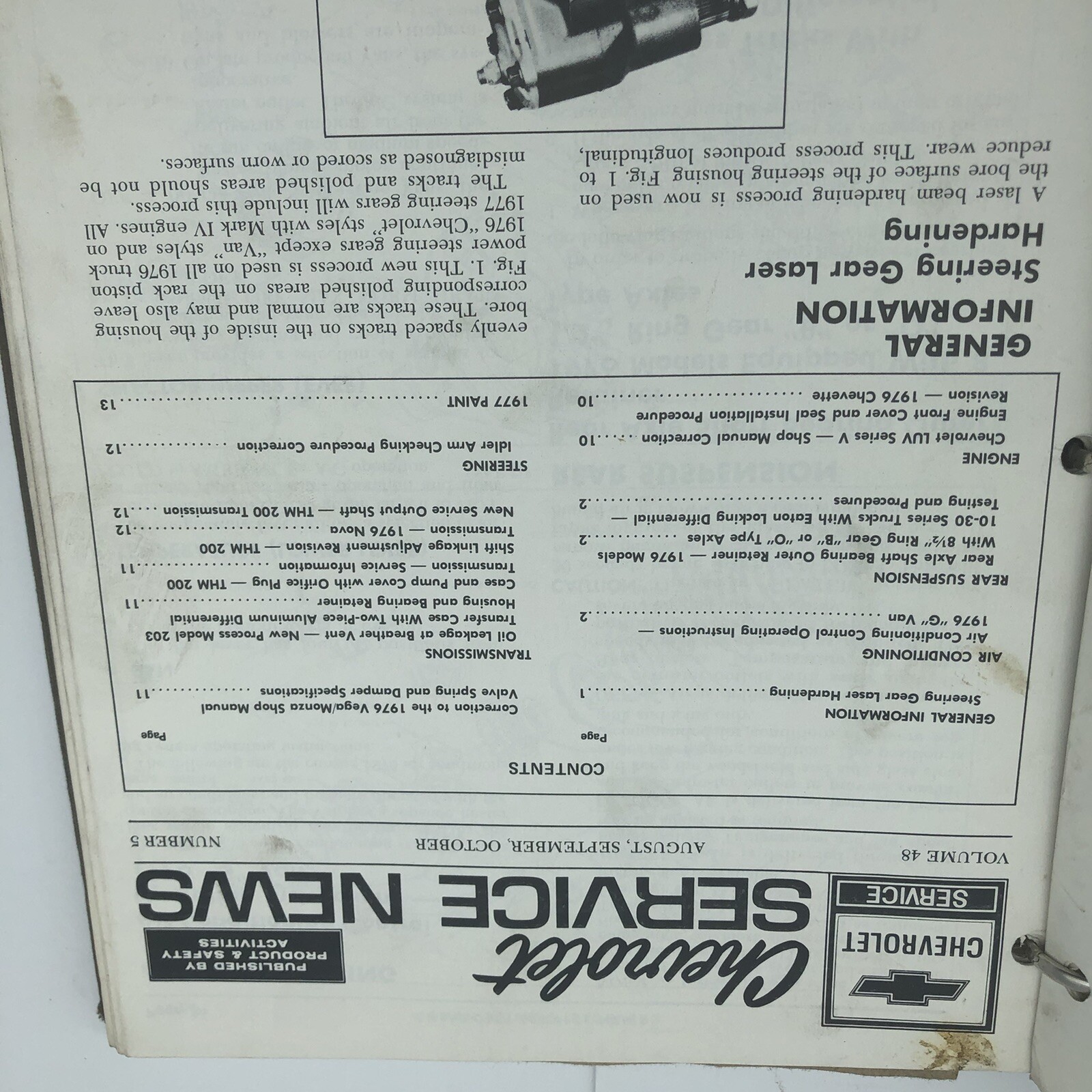
Chevrolet Service News, Volume 48, Number 5, headed August, September, October and copyrighted 1976, describes laser hardening of the steering-housing bore. The process produces longitudinal, evenly spaced tracks in the bore and may leave corresponding polished areas on the rack piston. Figure 1 labels both features.
The article expressly applies the process to 1976 truck power-steering gears, excluding “Van” styles. It separately identifies certain 1976 passenger-car applications and announces broader use for 1977; those statements should not be merged into the 1976 truck scope. This is documentation of a factory manufacturing process and its stated application. It supplies no assembly-plant identifier, exact production cutoff or date-code legend, and cannot authenticate a surviving gear or assess its present condition.
Source: “Steering Gear Laser Hardening,” Chevrolet Service News, Volume 48, Number 5, page 1; issue heading August, September, October, ©1976 General Motors Corporation. Public original-page photograph: Original article page . Gallery context: source gallery . A second photograph of the same page preserves the full masthead: full masthead photograph .

What an air-conditioning compressor plate can tell you
Chevrolet’s 1974 base manual places the model and serial numbers on a plate on top of the axial six-cylinder compressor. The 1976 supplement carries the earlier A/C information forward except for its stated changes. That locator belongs to the axial-compressor description; it is not a universal location or date decoder for every replacement unit.
Compressor cylinder count and engine cylinder count are separate descriptions. The 1976 supplement discusses a radial four-cylinder compressor for six-cylinder-engine applications. Its V8 overhaul coverage describes the six-cylinder compressor while retaining application differences in brackets, pulleys, connections and capacity. It also specifies a new expansion-tube type for 1976 C/K trucks, so the older manual cannot be applied without the supplement’s exceptions.
Read service numbers with their part descriptions. For example, GM’s February 1983 catalog lists 12300267 for its selected 1973–76 eight-cylinder truck applications as a compressor less clutch and pulley. That entry does not identify an entire A/C installation or establish that the number is physically marked on every original component.
Keep the observed plate text, compressor type, dated service reference and vehicle-linked factory or dealer paperwork together. A matching component description or C60 entry does not establish when the current compressor was installed. A 1976-applicable serial/date legend and a dealer-installed A/C kit/application reference remain unresolved.
Sources: Chevrolet ST-330-74, printed 1A-31 / PDF 55; ST-330-76, section 1A opening / PDF 27, printed 1A-9 / PDF 35 and overhaul section 1 opening / PDF 259. The two opening leaves do not show printed folios. GM Light Truck Parts Catalog 51, REV. 2-83, group 9.170, printed 9-3 / preserved PDF 1053; selected compressor entry covering CKGP1/2/3, Blazer, Jimmy and M.H.C., eight-cylinder, 1973–76. The later catalog is a service reference, not an original-production ledger or current interchange rule. The selected preserved catalog page was inspected; no verified public page URL is added.
Power take-off (PTO) provisions in factory literature
The 1976 U.S. Chevrolet supplement documents PTO covers for NP203, NP205 and CH465 components. Separately, Canadian Chevrolet pickup literature printed in September 1975 describes a PTO opening on the conventional transfer case in its manual-transmission four-wheel-drive context, and stationary PTO capability through the full-time system’s neutral position in its K-model pickup/Turbo Hydra-Matic context. The Canadian brochure does not name NP203 or NP205. [S1, overhaul 7M-15 and 7M-18 / PDF 345 and 348; Specifications 20-21 / PDF 390-391; S6, printed/PDF 9]
These passages establish component provisions and described capability. They do not identify a complete factory-orderable PTO accessory, a PTO RPO/SEO, accessory maker, gearing, output rating or actual factory installation on a particular truck. The brochure description is not an operating procedure, and its Canadian Chevrolet scope is not a general GMC or U.S. ordering rule.
What remains unresolved
- Complete 1976 GMC model-by-model ordering and restriction tables, and Canadian/Oshawa-specific component sourcing and marking practices
- Engine casting-number/date locations and decoding, a complete LF5/LS9 suffix crosswalk, and the exact engine-derivative location and literal format
- Complete 1976 transmission production, calibration, serial and date-code formats; a separately verified Tremec location; and NP203/NP205 identification-tag locations and legends
- The rear-axle source-location differences, complete per-code application restrictions, and complete 1976 front-axle production-date/source-character decoding and exact changeover
- The apparent M38/M40 disagreement in the previously documented vehicle record
- Delcotron calendar-date fields; physical steering/brake casting, assembly and date legends; exterior replacement-axle marking rules; and the exact 1976 C/K auxiliary-tank selector/gauge circuit and capacity-source reconciliation
- Complete PTO accessory ordering, compatibility and installation evidence
The service manuals and retrospective catalog now resolve specific location, suffix and rear-code questions. The remaining gaps above apply to the material checked; they are not a claim that no further factory source exists. None of these reference findings upgrades the originality status of a surviving truck.
Division and market boundary
This page describes the recovered Chevrolet pickup table. Chevrolet component usage is evidence of GM practice, but it is not a substitute for a complete 1976 GMC data book or dealer order guide. Canadian and Oshawa-built trucks must be evaluated from their own vehicle documents and Canadian records rather than being forced into a U.S. Chevrolet matrix.
For the separately dated California approvals, see the California certification source sequence.
Primary source
Chevrolet Motor Division, 1976 Chevrolet Truck vehicle information kit, “Pickup / Power Teams,” printed pages 27–28, each dated January 16, 1976. C-series combinations and axle notes, printed Page 27 (PDF 30); K-series combinations and engine ratings, printed Page 28 (PDF 31).
The 1976 engine VIN-character mapping is separately supported by Chevrolet and GMC Light Duty Truck Parts Catalog 51, 1973–1978, revised February 1983. That later printing is useful corroboration, but the model-year data book controls the availability statements on this page.
Component-identification source references
PDF page numbers are one-based and refer to the preserved scans used in the October 1–3, 2026 research. Printed service and overhaul folios can repeat inside S1; the named half is retained. The text above paraphrases the evidence; no source-page images are included.
S1. Chevrolet Motor Division, General Motors Corporation, 1976 10-30 Series Truck Chassis Service and Overhaul Manual Supplement, ST-330-76. Copyright 1976; printed in the U.S.A.; no narrower issue date established. Title and foreword: unnumbered / PDF 5. The foreword expressly supplements the 1974 base manuals. Locations cited: service 0-1 / PDF 7 and 0-3 / PDF 9; service section 3 opening / PDF 45; overhaul section 3 opening / PDF 297; overhaul 7M-15 and 7M-18 / PDF 345 and 348; Specifications 20-21 / PDF 390-391. Additional carburetor references: service 6M-31 / PDF 119 and 6M-54–55 / PDF 140–141; overhaul 6M-1 / PDF 309; Specifications 13 / PDF 383. The section-opening leaves at PDFs 7, 45 and 297 lack a printed folio; section numbering is identified by the surrounding contents/pages. Source examined October 1, 2026. Additional pages checked October 3, 2026: service section 6Y opening / PDF 173 and section 8 opening / PDF 211; overhaul section 4 opening / PDF 299 and section 5 opening / PDF 301; Specifications 17 / PDF 387. The cited section-opening leaves lack a visible folio. The Section 8 illustration is P30-specific.
S2. Chevrolet Motor Division, 1974 Light Duty Truck Series 10-30 Chassis Service Manual, ST-330-74, printed 3-38 / PDF 216. Relevant 1974 front-axle information is carried forward by S1, subject to its listed changes. Source recorded in the October 1, 2026 research. Also cited: 6Y-22 / PDF 562, the 10-SI Delcotron rated-output stamping statement, used with S1’s section 6Y carry-forward and stated changes; checked October 3, 2026.
S3. Chevrolet Motor Division, 1974 Passenger Car and Light Truck Overhaul Manual, ST-333-74, copyright 1973; printed 3-1 / PDF 23 and 7A-70 / PDF 290; 6M-2 / PDF 188, figure M1, 4M identification view. The cited truck/front-axle and TH350 procedures and the 4M identification diagram are used here; the book also covers passenger cars. Source recorded in the October 1, 2026 research. Also cited: 4-45 / PDF 77, Power-Lok service alignment mark, and 4-55 / PDF 87 plus 4-58–59 / PDF 90–91, Dana 10½-inch rear-axle scope, matched gear-set numbers and pinion-depth marks. These passages are used with S1’s section 4 carry-forward and stated changes; checked October 3, 2026.
S4. General Motors Corporation, Warehousing and Distribution Division, 1973-78 Truck Parts Catalog, Light Duty Models, Series 10 thru 35, Catalog 51, effective February 1983, pages marked REV. 2-83. Retrospective factory service-parts evidence. Relevant pages: TP7 / printed 7 / PDF 11; TP17 / printed 17 / PDF 21; TP23 / printed 23 / PDF 27; lower 1976 portion of TP27 / printed 27 / PDF 31; printed 4-27 / PDF 597. The 1975 material above the 1976 axle table and the 1977 material beginning after the 1976 engine continuation are outside the cited 1976 entries. Public scans checked October 2, 2026 are hosted by the independent GMPartsWiki archive. Additional retained-scan pages checked October 3, 2026: 6-17 / PDF 945, group 6.508, steering gear descriptions, and 6-38 / PDF 966, group 6.803, housing assembly 7828050. These are retrospective service-parts entries; no physical casting-number equivalence is established.
S6. General Motors of Canada Limited, Pickups: Your Money's Worth, Mile After Mile After Mile, printed in Canada, imprint 9/75 on the unnumbered back cover / PDF 12; relevant printed/PDF page 9. The preserved scan has 12 pages. The cover says Pickups; the archive's 1976 attribution is separate from the directly verified September 1975 imprint. Public source checked October 1, 2026: The Old Car Manual Project, an independent archive, presents the brochure in seven image views covering the 12 printed pages. Printed page 9 on the pages 8-9 spread; back-cover Canadian publisher, date and imprint; cover. These are archive-hosted image views, not the preserved PDF's page numbering. No source image is reproduced here.
S7. Chevrolet Motor Division, 1976 Chevrolet Truck Camper Loading—Consumer Information, August 1975, printed/PDF pages 32–33 and 39. The preserved scan has 62 pages. These are dated Chevrolet pickup option descriptions, not a complete GMC or Canadian ordering matrix. Recorded archive URL; live access not verified. Selected pages checked October 3, 2026.
Have original identification records?
Clear photographs of engine stamps, transmission tags, transfer-case tags, axle-tube markings, SPID labels, build sheets, invoices, and warranty records can help close the remaining gaps. Partial evidence is welcome, but markings should be photographed before cleaning or alteration.